Where to Start
Radiosonde tracking
What is Radiosonde? Every day, every main city sends a balloon up for weather measurements. These balloons float around until the burst and fall to the groud. On the ground they are fare game for anyone to grab, after all they are a form of rubbish at that point. This sounlds like a cool idea for “fox hunting” these transmitters.
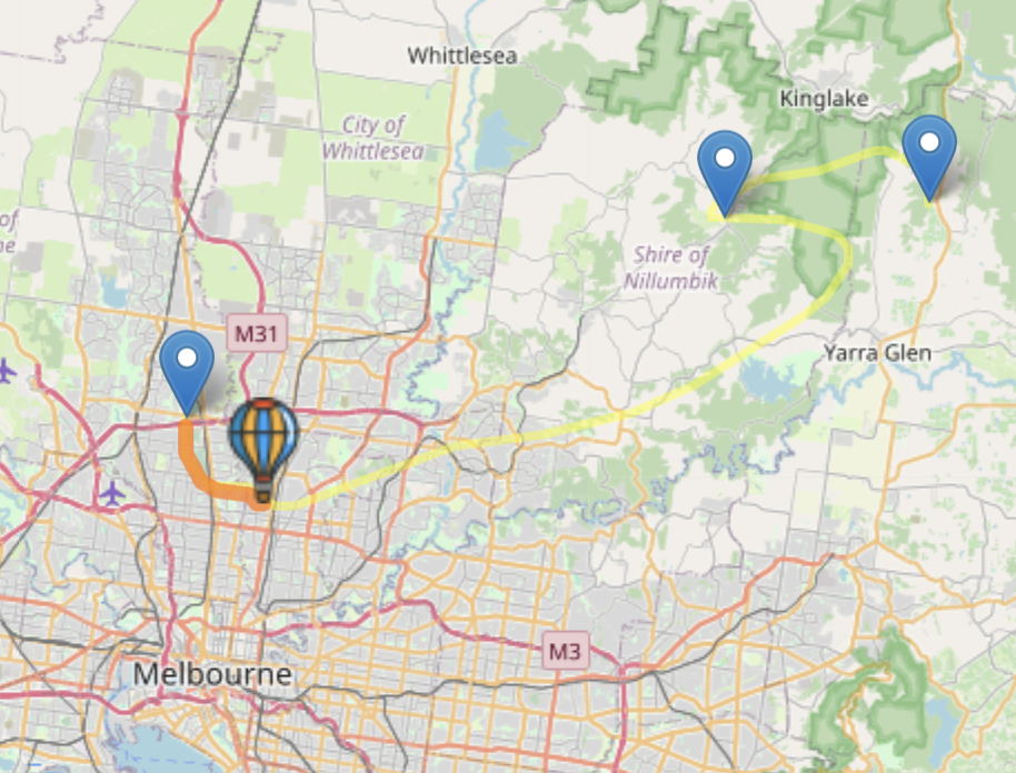
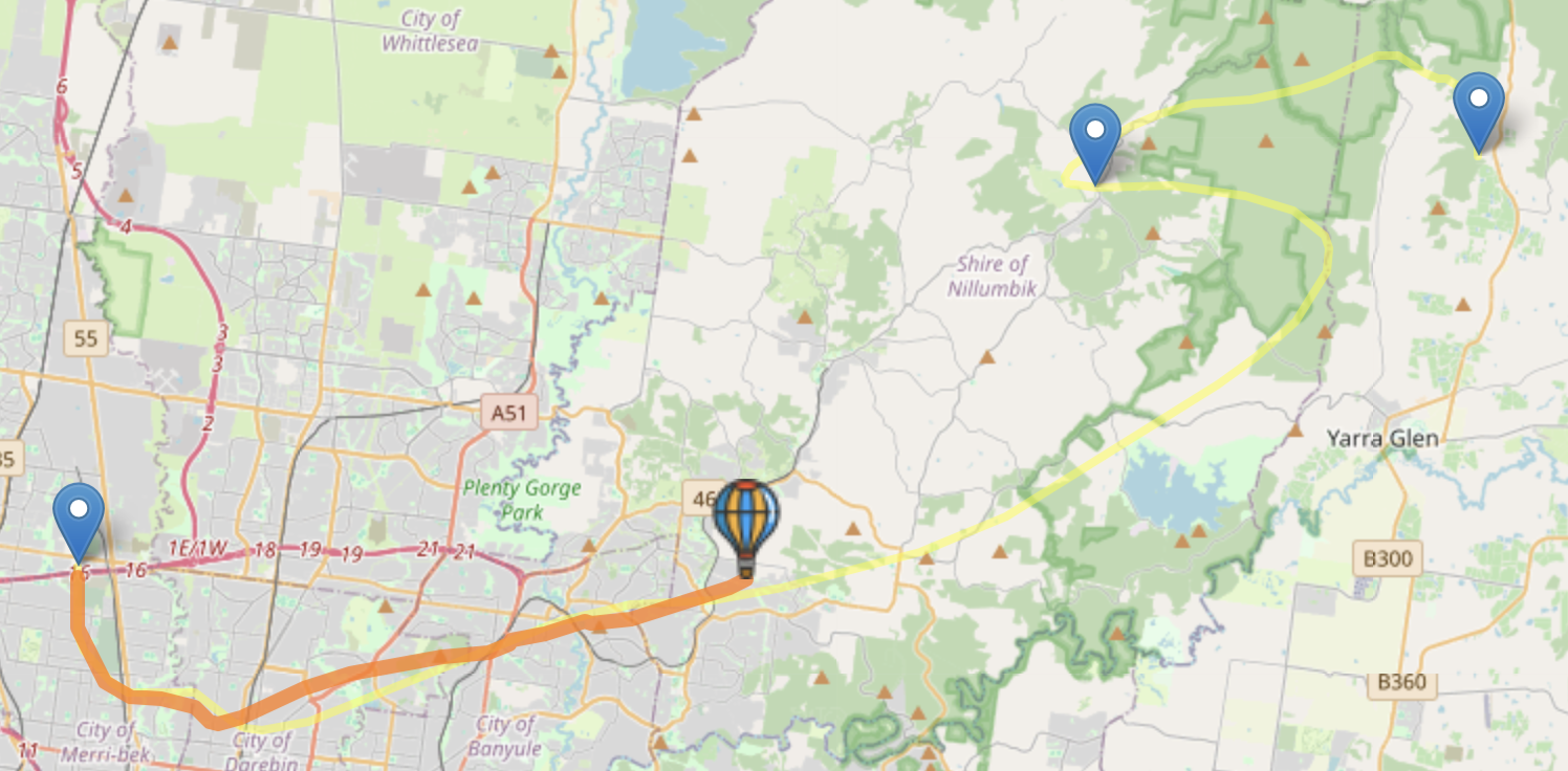
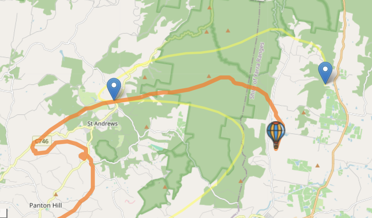
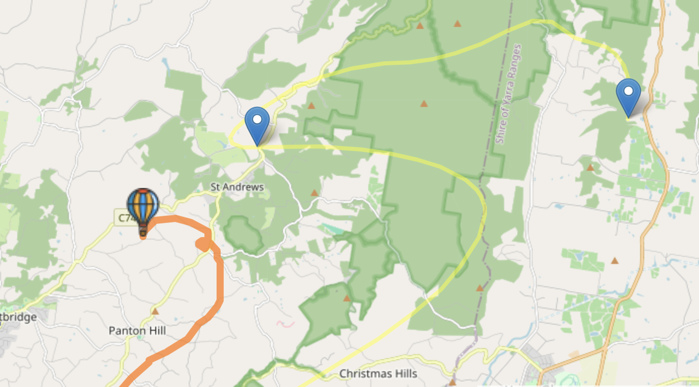
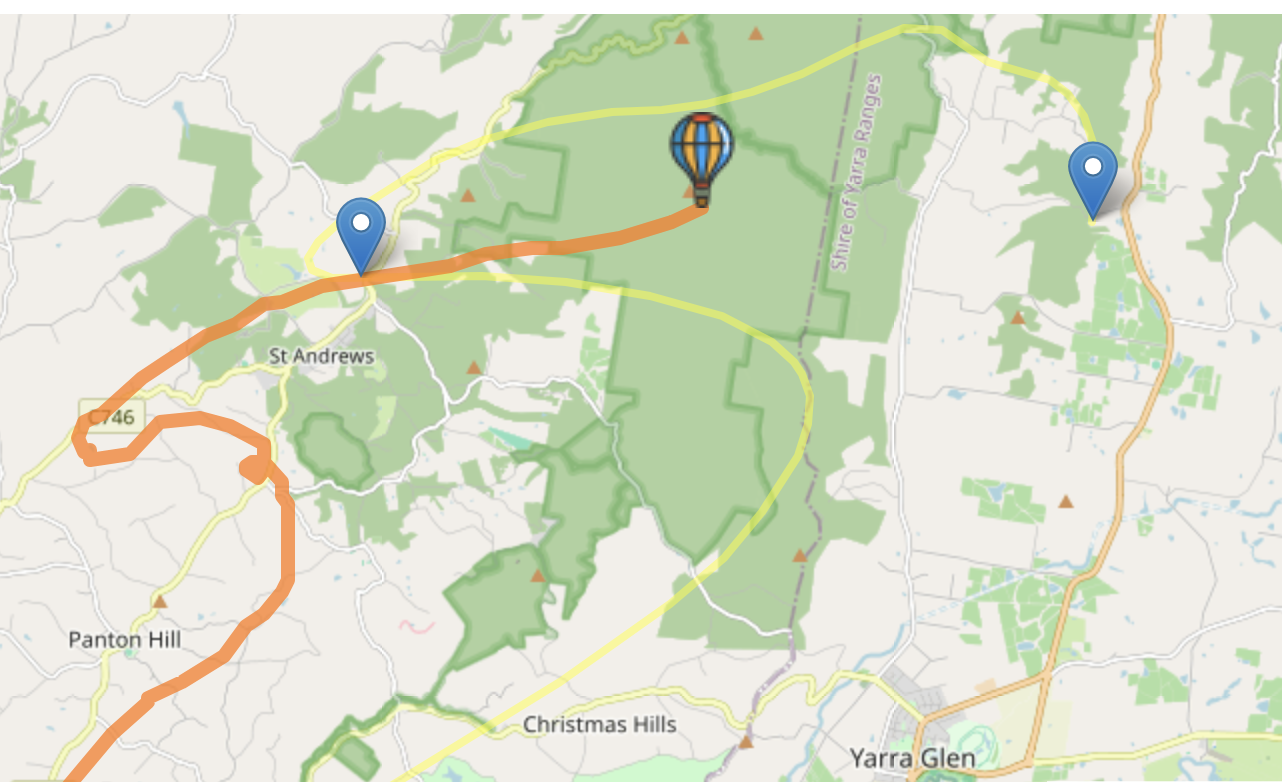
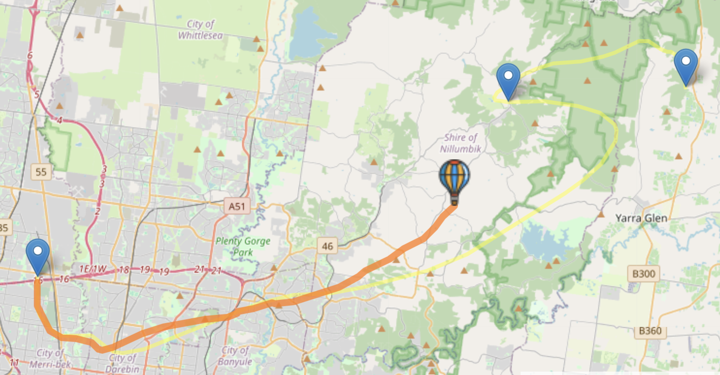
In Melbourne it seems to be sent at 10am from the airport. As the balloon floats up it transmits GPS and a bunch of weather data. There is site - https://radiosondy.info/ - which tracks the signals from the balloons, draws them on a map as well as plots the prediction of where a balloon will fly. There is even a leaders board for those who register that they have found such a radiosonde.
1 such radio sonde was sondenumber: U2840056
I found a couple of resources on tracking these radiosondes
- https://www.klofas.com/blog/2020/two-months-radiosonde-reception/
- focusing on analysing the signal strength vs GPS location
- YouTube - How to track & recover a NWS weather balloon & radiosonde 🎈🎈 Ham
Radio DIY - by Overlook Horizon
- A more practical view on how to track these devices and find them

Looking back at sondenumber:
U2840056 it says it
transmits on 400.500 MHz (and the others in Melbourne transmit on 401.500
MHz) so it was time to rummage about and find a receiver I may have to pick
these signals up. Finally I pulled out an old RTL-SDR USB dongle I had around,
never before connected successfully to my computer, and thought let’s give it a
go. And sure enough after finding that I should use GQRX and I could install it
with brew
brew cask install gqrx
I put an old scanner antenna on it, walked out the back and heard the distictive sound of a Radiosonde transmission - success. Now to build a rig to track these and actually find them.
Radiosonde fox hunting rig
- RTL-SDR seems a good fit
- the GQRX software is ok
- but I would need a more mobile rig, so I should look to switch to a RasPi
- with an external monintor and mount as well as power
- it would be good to have a directional antenna, maybe a yagi
- it would be good to also have an omni directional antenna
- maybe an RF switch to switch between the antennas
- maybe even an RF amplifier
- and a GPS so I could compare where I am and the Radiosonde is. This would help point the directional antenna in the right direction as well as predict how far to walk when it has finally fallen on the ground. Maybe this is a smaller headsup display on an OLED.
With my head spinning with ideas I thought it would be worth investigating some of them.
Run it on a RasPi
I think the first next step would have to be to run it on a RasPi, make sure it compiles and is performant. That and getting the Radiosonde decoder software working to get live metrics and location from the Radiosonde.
There seem to be some good resources here
- https://github.com/tkerr/rpi-sdr?tab=readme-ov-file
- https://github.com/tkerr/rpi-sdr?tab=readme-ov-file#software-needed - including how to burn the image
- http://www.om3bc.com/docs/SF/sondefinder_en.html
Decoder
Probably would be best to decode your own signals. According to [https://www.rtl-sdr.com/tutorial-on-using-rs-to-decode-and-plot-radiosondes/}(https://www.rtl-sdr.com/tutorial-on-using-rs-to-decode-and-plot-radiosondes/) RS is the free program of choice
- https://github.com/rs1729/RS
- there is mention of a tutorial on https://www.happysat.nl/Zilog/decoder.html
- which can be accessed via way back machine
https://web.archive.org/web/20180909213658/http://www.happysat.nl/Zilog/decoder.html
- the images seem to be missing but there is a bunch of install instructions which could come in handy
- which can be accessed via way back machine
https://web.archive.org/web/20180909213658/http://www.happysat.nl/Zilog/decoder.html
Antenna
Next would probably be making a resonable directional antenna, like a Tapemeasure Yagi
- simple tape measure Yagi
- an an omnidirectional
- more on cheap tape measure Yagi
- https://www.instructables.com/433-MHz-tape-measure-antenna-suits-UHF-transmitte/
-
and the supposedly original article that made them popular, on wayback machine waybackmachine: http://pages.videotron.com/ve2jmk/tape_bm.htm
copied here for posperity
/ham-radio/archives/pages.videotron.com_ve2jmk_tape_bm.htm.html
- some of these are around
433MHzband because of the cheap short distance transmitters available there Electroncs stackexchange: Why do my 433 MHz receiver and transmitter modules not work reliably?- specific antenna for How To Make a 433 MHz Yagi Antenna Design For A Long-range?
- and a lot of book recommendations Quora: What is the best book for learning how to build antennas?
- also
- 1/4 wave ground plane antennas
- turnstile antennas
- home made coaxial with some interesting images
- loaded coil - 433 MHz Coil Loaded Antenna
- helix antenna
- dipole length calculator
which sends me down the rabbit hole of how to calibrate it and weather it’s time to get something like a NanoVNA? the other thing I want to get is a TinySA Ultra! for frequency analysis! so many things, so little money and time to sort out which to play with.
RF switch
- 1PCS 6GHz RF Switch Module Single pole double throw for Ham Radio Amplifier Module HMC349
- HMC7992 0.1-6Ghz RF Switch Module Single Pole Four Throw Switch
Non-Reflective
- https://www.aliexpress.com/item/1005004757395491.html
- Building an RF Switching Unit
- https://community.element14.com/technologies/test-and-measurement/b/blog/posts/building-an-rf-switching-unit
- built using RENESAS F2912NCGI - RF Switch, 9kHz to 9GHz, 2.7V to 3.6V Supply, TQFN-20
- https://au.element14.com/integrated-device-technology/f2912ncgi/rf-switch-sp2t-9khz-9ghz-tqfn/dp/2828538
- or 8 way switch RF Switch Module 1 Open 8 RF Radio Communication Electronic Component HMC253
RF amplifier
- 4W 36DB 1-800Mhz VHF UHF RF power Amplifier F/ Ham Radio HF FM transmitter Walkie talkie Short wave 868M 915M LORA Helium Miner
- 20-3000mhz RF Wideband Amplifier Gain 40dB Low Noise Amplifier LNA Board Modules DC 5V for FM HF VHFf/UHF
- https://www.aliexpress.com/item/1005005577405215.html
RF Power meter
- 1MHZ-8000MHZ 8GHz RF power attenuation OLED display RF power meter value
  digital meter 500MHZ 3GHZ+ Sofware 10W 30DB Attenuator
- [https://www.aliexpress.com/item/1005005431698851.html](https://www.aliexpress.com/item/1005005431698851.html)
RTL-SDR software
for Mac
- GQRX
- https://www.gqrx.dk/
- following - https://www.turais.de/install-gqrx-in-mac-os-x/
brew cask install gqrx - select
Realtek RTL2836Ufor teh Device and mostly everything worked - does raise an interesting point of having a USB Port isolator, as after all you may have an outdoor antenna connected to a dongle to an expensive computer. I think the idea is to move it to a Ras Pi as soom as possible
- something like Douk Audio ADuM4160 USB to USB Isolator Module Audio Noise Eliminator Industrial Isolator Protection 1500V Digital Module sounds good but according to the article does not work with the RTL-SDR - https://www.aliexpress.com/item/32909293430.html
- could it be used as a scanner?
- Reddit: Using GQRX-scan as a “poor man’s police scanner” for analog trunked radio on Linux / Raspberry Pi
- https://gitlab.com/khaytsus/gqrx-scan
perl gqrx-scan --type gqrxfile --pause 0.2 --wait --delaytime 0.2
according to https://www.rtl-sdr.com/tag/macos/
- LocalRadio https://github.com/dsward2/LocalRadio - seems out of date
- waveSDR - also fairly old https://github.com/getoffmyhack/waveSDR
YouTube - MacOS Desktop RTLSDR Application written in Swift by GetOffMyHack

Morse practice key
Keen to bring some of this interest into my scout troop. The idea is to bring a morse code practice key to a scout meeting. Then slowly build on the idea:
- maybe have them build their own key out of some springy steel
- build a simple transmitter
- build a transmitter over something like an ESP32 and wifi?
- maybe using an ESP32 mesch you could have a bunch of scouts communicate together in the bush?
- ESP32 mesh
- bunch of ideas on keyers
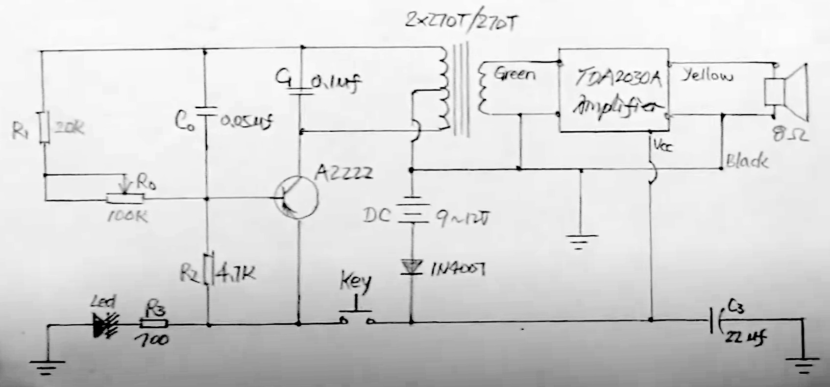
Center tapped transformer audio oscillator
https://www.next.gr/circuits/CENTER-TAPPED-TRANSFORMER-AUDIO-OSCILLATOR-l53755.html
The oscillator circuit uses a center-tapped transistor output transformer to serve as a load for the collector of Q1, supply a feedback signal for the base, and serve as the output winding for driving the speaker. R1 supplies dc bias and C1 completes the ac path from the transformer to Q1’s base. You can play around with the values of C1 and R1 to change the oscillator’s output level and tone, but don’t reduce R1’s value too much or the transistor will draw excessive collector current.
![]()
How To DIY A Morse Code Practice Oscillator?

fundementally
ARRL Morse Code Oscillator
https://www.arrl.org/shop/files/pdfs/Morse%20Code%20Oscillator.pdf
basically
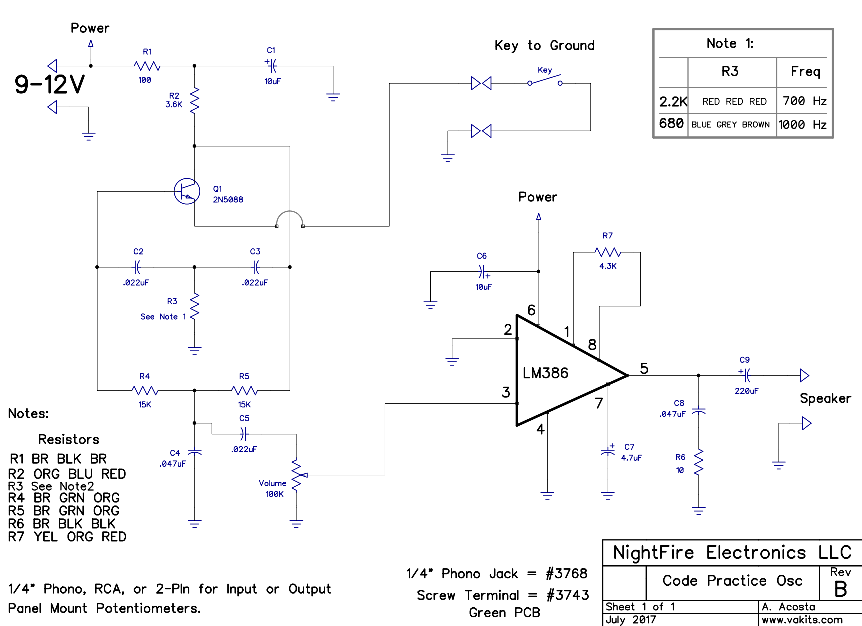
NightFire - code practice oscillator kit
This Code Practice Oscillator Kit is a very popular and practical device used in Ham Radio for practicing your Morse Code. It is designed as a One-Transistor, Twin-Tee, Audio Phase-Shift, Sinewave Oscillator with an Audio Amplifier on the output.
The kit produces a very clean sinewave of 700Hz
Note: 700Hz is extremely popular and very pleasing to the human ear.
https://vakits.com/code-practice-oscillator-kit-w-phono-jack-3768
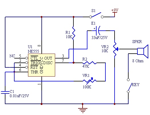
Electroncis Project Design - code practice oscillator
https://www.electronics-project-design.com/CodePracticeOscillator.html
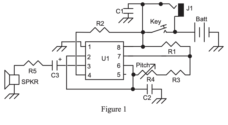
another 555 based design
Morse code decoder
Jaycar has one
https://www.jaycar.com.au/morse-code-decoder
using a 567 Tone Decoder IC
-
more about the
567here https://www.homemade-circuits.com/lm567-tone-decoder-ic-features-and/ -
and this selection of other morse code trainer circuits https://www.homemade-circuits.com/morse-code-practice-oscillator-circuits/ also has one using a
567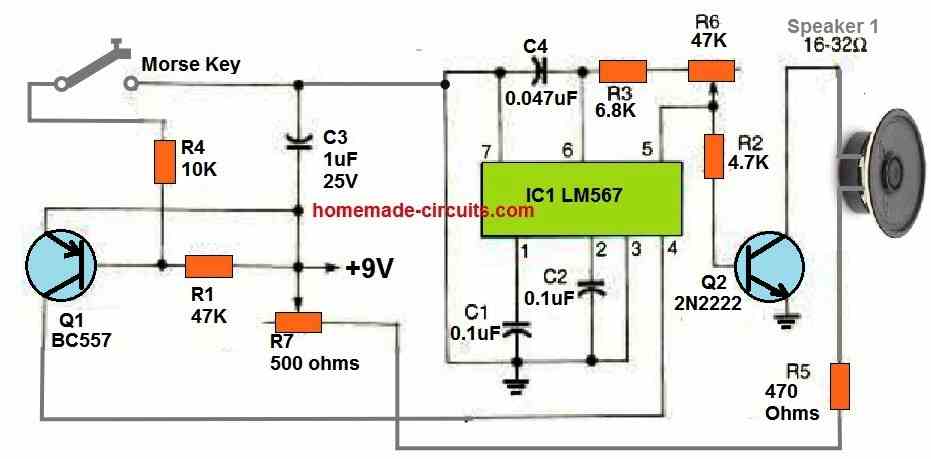
the rest of the article is worth checking out for other oscillators, minitransmitters and receivers.