Why Yagi Director so close?
Yagi for 400MHz Radiosonde finding
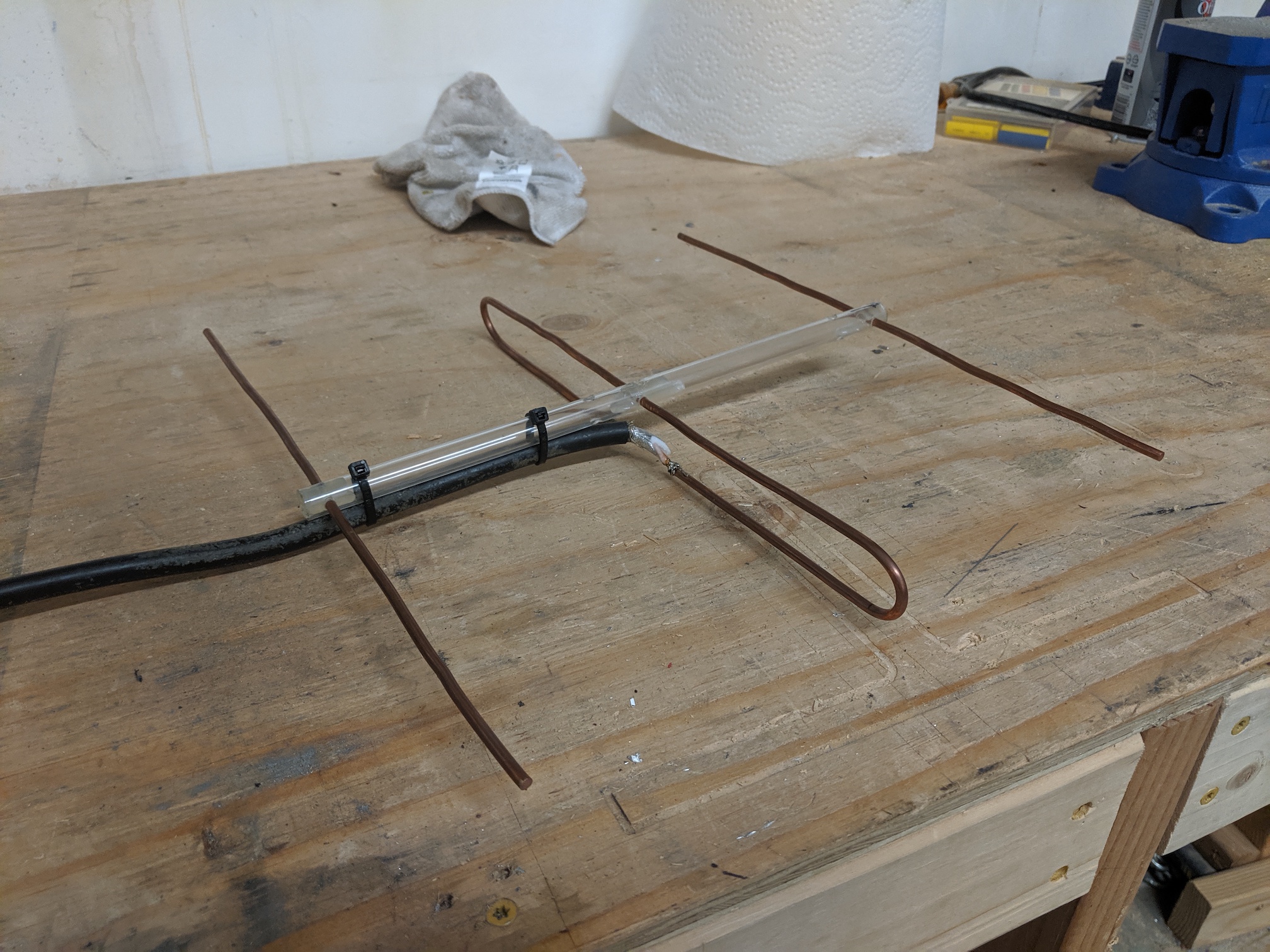
Finally started making a tape measure yagi antenna for radiosonde direction finding. I want it quick and ready by this weekend in case I happen to be around a falling radiosonde, as I will be out and about on activities with the kids. So I got to building a 3 beam 400MHz Yagi using tape measure on a polypropolene irrigation pipe frame. First I started with an old standard size, 25mm (1 inch) wide tape measure, only to find out I didn’t have the right cross pieces so I switched down to a 12mm wide tape measure and 13mm polyprop pipe. I reached for the first best Yagi calculator I could find.
-
https://www.changpuak.ch/electronics/yagi_uda_antenna_DL6WU.php
  REQUIREMENTS
  ------------
  Freq. [MHz]                           400
  Boomlength [m]                       [  0.260 ] calculated
  Gain [dBd] (approx.)                 [  5.23  ] calculated
  Elements                                3
  Diameter of parasitic Elements [mm]    12
  Diameter of Boom [mm]                   0
  Is the boom isolated from parasitics ? ✅ [yes]   [no]
  [SHOW ME THE DETAILS]
spat out
-
DESIGN DATA FOR YOUR YAGI
  https://www.changpuak.ch/electronics/yagi_uda_antenna.php
  Javascript Version 12.01.2014, based on Rothammel / DL6WU
  -------------------------------------------------------------
  Frequency     :  400  MHz, (useful from 392 to 408)
  Wavelength    :  750  mm
  Rod Diameter  :  12  mm
  Boom Diameter :  0  mm
  Boom Length   :  260  mm
  d/lambda      :  0.016    ( min.: 0.002 , max.: 0.01 )
  D/lambda      :  0.010    ( min.: 0.01 , max.: 0.05 )
  Elements      :  3
  Gain          :  5.23 dBd (approx.)
  -------------------------------------------------------------
  Reflector Length   : 362 mm
  Reflector Position :  0 mm
  -------------------------------------------------------------
  Dipole Position    : 180 mm
  -------------------------------------------------------------
  Director #1 Position : 236 mm ,  Length : 341 mm
  Distance Dipole - Dir. #1 : 56 mm
  -------------------------------------------------------------
  Directors / Parasitics are isolated.
  Please choose an isolater thicker than : 4 mm
and started cutting things up. I noticed there was a bit of a tight fit between the director and dipole but had seen similar tight fits in some videos so I thought I was going OK.
But looking at my finished product, I couldn’t help but thinking that
- that director (on the left) is way close to the dipole (center beam)
- how does
Diameter of Boom [mm] 0
make sense anyway? because it is polyprop?
- and
"Is the boom isolated from parasitics ? ✅ [yes]"
are we suggesting it can be 1 hunk of joint metal?
- where is the “hairpin” some mention?
- do I need some matching?
- what is
d/lambdaandD/lambda? - and where is the calculation for the dipole anyway? this took me a whole
bunch of time to find that I need to actually click the Combine it with
straight dipolelink at the top, which in turn gave me
  Frequency [MHz]       400   Length units [  mm  ]
  Diameter D             12   Length A     [ 177.9]
  Half Wavelength [ 374.75]   Reduction    [ 0.949]

  [CALCULATE]
This opens up a whole nother can of worms with the
Gap Gbeing mentioned but it’s not clear what the distance is meant to be? in the comments it sounds like the smallest possible? Also there is a 1:1 transformer? whoa when did this come into play? in fact the page goes on to mention that they double check the results of the calculator in the lab
using a
ETC1-1-13TR (1:1, 5 MHz - 3 GHz)

NOTE the tape measure article I archived
/ham-radio/archives/pages.videotron.com_ve2jmk_tape_bm.htm.html
also available online http://theleggios.net/wb2hol/projects/rdf/tape_bm.htm
does actually mention the gap. The construction there is to use hose clamps for the driven dipole elmenets so that the gap can be changed. A gap of 1 inch seemed to be just right for the lowest SWR on the 144MHz (2 meter band). There is also a discussion of the “hairpin match”. Simply a 5 inch pice of wire. The idea is that the wire has just the right amount of inductance, to cancel the capacitive reactance and produce a good match.
I am hoping my investment in NanoVNA and TinySA will help me find the optimal values for 400MHz radiosonde finding, although given it’s a receiveing antenna it may not matter all that much.
What made it worse is that I originally plugged in my diameter for the beam as 25mm for the standard tape measure. When I switched to the 12mm tape measure I noted that the director didn’t change size so assumed all the other sizes were the same - which they were not. So it is quite likely that my first antenna is not tuned to anything. But I still have all these questions, so I went looking.
-
certainly there seem to be antennas with the director close to the dipole
-
but there are plenty where that is not the case
The above image from the article THE YAGI-UDA ANTENNA: AN ILLUSTRATED PRIMER using the same article as me!!! so why the disparity?
A three-element Yagi-Uda is kind of an edge case so I used a calculator designed with that constraint in mind
and
For the final product I made a 10-element Yagi-Uda antenna. I used a different calculator created for antennas with a variable number of elements: https://www.changpuak.ch/electronics/yagi_uda_antenna_DL6WU.php
the difference the DL6WU bit. So I had used the DL6WU calculator which
sounds like it is for more directors and the first one, without the DL6WU is
the special case 3 elementYagi?
This article also filled in a few details for me, like the fact that the boom can be conductive or non conductive, it will just alter the dimentions. Also
These calculators usually assume you’ve already built this kind of antenna in the past and spit out a list of measurements, which can be kind of intimidating for someone who doesn’t know what they’re doing.
you bet they do. But I guess I have 1 antenna under my belt? maybe 1/2 as it’s probably not very well tuned to anything. Continuing reading the article
Normally the reason that you’d choose to use a folded dipole instead of a half-wave dipole when constructing a Yagi-Uda antenna is to more easily match the impedance of the coax you’re attaching to it. While this is a nice property, it really only matters for antennas that also transmit, which we aren’t.
Right, another thing that has been confusing me, everything is about 50Ω impedence matching and a dipole is 50Ω but a folded dipole is 200Ω. As I see now this does not matter so much when receiving.
In part 2 of the article he does build a 10-element Yagi and uses PVC pipe and puts in the 21mm diameter in to the calculator!!! so the diameter should always be there? irrespective of it is conductive or non-conductive boom material?
The final design does have the director a whole lot closer to the dipole but as there are so many directors it does not stand out so much. Not that looks matter, but certainly it makes you wander how close you have got with a design.
I did end up coming across a discussion on ham_radio:yagi_antenna
Now with todays computer generated optimization I notice the first director is very close in front of the driven element
inside was a bunch of interesting commentary which made it sound like there is a lot more to this, and simulations and acutal experimentation and a bunch of the dimentions are not so easy to just calculate.
scouring links via http://www.wa1mba.org/ and http://www.wa1mba.org/yagiinfo.htm led me to the source of some of these ramblings at http://www.wa1mba.org/Perfect%20Yagi%20Charts2.pdf
But probably the best quote is the end here
The most critical of 432 yagis were developed by K2RIW, his 19 element design. He demanded element length precision to +/- 1/64th inch, and when that care is taken that yagi comes up at 15.05 to 15.1 dBd at antenna measuring contests. Its so consistent that its the US standard gain reference for 432. With a pair of them at about 75 feet, I’ve heard CW signals off the moon at moon rise by ear without a preamp on the radio.
In the end I put DL6WU into search and found another site which looks a lot
more on the money
The calculator calculates the Yagi-Uda antenna of the DL6WU design with boom-correction (correction for the influence of the load-bearing boom). Calculation is according to the G3SEK-DL6WU method. The antenna is optimized for maximum gain. The design feature of the DL6WU is that the number of passive elements can be increased / decreased without noticeable changes in SWR, which made it possible to create such a calculator. It is believed that DL6WU antennas, having a very high gain, are less capricious about the presence of outside objects near them and retain their characteristics under any weather conditions.
Right so the DL6WU is a calculation method! this site came with it’s own
similar calculator and a more detailed image

Importantly inlcuding
Dimensions of the matching coaxial cable (balun).
so this “hairpin” can actually come with a proper calculation. Again I presume this is more important for a transmitting aerial. Further down there is a link to Gamma Matching which has a lot more detail on one of the matching types. The type that is often a parallel rod to the driven element with a connector that can be moved up and down the driven element to tune. All this and another missing thing from a lot of calculators, some links to back up the sources
-
C. A. Balanis, Antenna Theory: Analysis and Design (3rd ed.)
John Wiley & Sons, Inc., pp. 531-538;
- Omega and Gama Matching
- Beam Matching L. B. Cebik, W4RNL (SK)
- Are gamma matches as bad as all that
Back to this final calculator, there is detail around various build types and it suggest 3 types of boom
- elements pass through and are electrically connected to a metal boom (boom correction 1)
- elements pass through but are electrically isolated from a metal boom (boom correction 50%)
- elements are mounted on a di-electric boom (boom correction 0)
The calculator page goes on to detail a number of measurements and models used as well as different profile booms and the lot. There is even a link to an Android App, Cantennator for performing some of these calculations. Almost too much info to digest, but certainly the background makes me understand a lot more of what is going on and how potentially flawed some online calculators may be.
There is also a 3 beam Yagi page
I want to immediately warn visitors to this page from a common mistake. If an anonymous person who got here intends just to calculate the dimensions of a “3-element Yagi-Uda antenna” according to some equations, then he will be disappointed.
Oh boy, just give me the antenna dimentions!!!
Somehwere in all this is another page about How to calculate an antenna
with a whole lot of math, analysis and a link to a python script that supposedly can take hours to calculate an antenna.
- https://github.com/nikiml/nec.opt
- with links to a dead page http://mladenov.ca/%7Enickm/scripts.html with no
history on web archive, just the landing page
- https://web.archive.org/web/20210722050107/http://mladenov.ca/~nickm/
So let’s give calculation 1 more try
using the original site but NOT DL6WU
-
https://www.changpuak.ch/electronics/yagi_uda_antenna.php
  REQUIREMENTS
  Freq. [MHz]                          400
  Boomlength [mm]                    [ 300 ] calculated
  Gain [dB] (approx.)                [ 6.8 ] calculated
  Elements                               3
  Diameter of parasitic Elements [mm]   12
  Diameter of Boom [mm]                 13
gives
DESIGN DATA FOR YOUR YAGI **** YAGI UDA ANTENNA **** Design by www.changpuak.ch --------------------------------------------------- Frequency : 400 MHz Wavelength : 750 mm d/lambda : 0.016 ( min.: 0.001 , max.: 0.04 ) D/lambda : 0.017 ( min.: 0.002 , max.: 0.04 ) Boomlength : 300 mm Elements : 3 Gain : 6.8 dB (approx.) --------------------------------------------------- Reflector Length [mm] : 360 Reflector Position [mm] : 0 --------------------------------- Dipole Length [mm] : 362 Dipole Position [mm] : 150 --------------------------------- Director Length [mm] : 329 Director Position [mm] : 300 --------------------------------- Calculations based on NBS TECHNICAL NOTE 688 Length might be slightly too long. Manufacturing Tolerances : < 2 mm -
Javascript Version 2022-06-13 by Valery Kustarev
3-elements UDA YAGI antenna
---------------------------------------------------
Frequency f: 400 MHz
Wavelength λ: 749 mm
Element diameter: 2.5 mm…7.5 mm ( min.: 0.003λ , max.: 0.01λ )
Approx. antenna gain: 7.3 dBi
Bandwidth by VSWR < 2: 28 MHz (approx.)
---------------------------------------------------
Reflector length R: 387 mm
---------------------------------------------------
Dipole length V: 351 mm
Dipole-reflector distance S1: 129 mm
---------------------------------
Director length D: 319 mm
Dipole-director distance S2: 103 mm
---------------------------------------------------
Minimum boom length Bl: 240 mm
in summary
for 12mm tape measure on 13mm polyprop pipe
| length | www.changpuak.ch | JS by Valery Kustarev |
|---|---|---|
| Gain | 6.8 dB | 7.3 dBi |
| Reflector Length | 360 mm | 387 mm |
| Reflector Position | 0 mm | 0 mm |
| Dipole Length | 362 mm | 351 mm |
| Dipole Position | 150 mm | 129 mm |
| Director Length | 329 mm | 319 mm |
| Director Position | 300 mm | 103 mm |
| Boom length | 300 mm | 240 mm |
So clearly I have another antenna to build with some new dimentions, or maybe I build bothand compare?