Talking Yagi at MERC
Another day another Yagi
After yesterdays deep dive on Yagi calculators and my, what looks like, lob sided yagi, it was time to put the learnings to good use, use the other calculor and build a “better looking” Yagi. Ofcourse the proof is in how well it works, and once I get a NanoVNA, how well it measures up. Having already attempted a build with polyprop and tape measure I had a bunch of learnings
- cut straight, with a blade and not a saw. The saw leaves the end too rough and it’s too hard to clean up.
- found a better way of cutting, basically clamp the blade and spin the plastic, this allowed for a straight cut.
- pre-measure all the separators - makes it easier to cut and it should be all the right distance once put together. - but maybe fine tune it before you cut it? more on that later
- take it easy with drilling the holes - still made a mess here on a couple of them
- file still seems the best way to take the barbs off
- use cable ties till I get a chance to tune the gap in the dipole
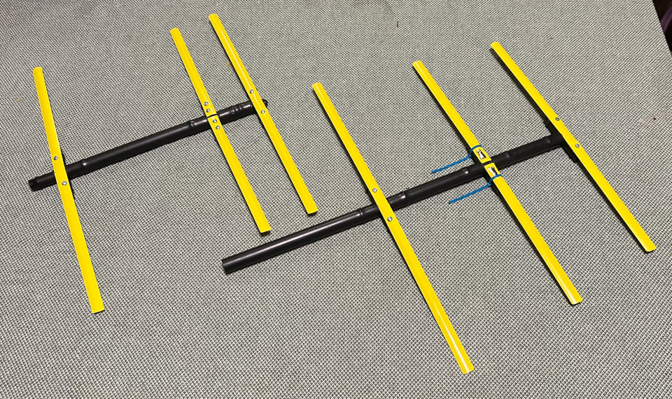
looks a bit better! Unfortunately still have not managed to connect it to my radio, as even though I bought some RG58 cable, and BNC connectors and a BNC to SMA converter, I could not seem to join the cable to the connector as the wire was too thick. This made me more eager to go to that nights local HAM meetup with MERC (Melbourne Electronics and Radio Club) to try and sort this out. This and a question around grounding antennas for safety from thunder storms and maybe some info about programing the Quansheng UV-K5.
I roll up and was ready for opinions to fly high. Firstly I was accused of buying 75Ω TV coax. Even when they looked at the slightly thiner RG-58/U clearly marked as such they argued about the fact it had a solid core and it needs a stranded core. Later that night someone more knowledgable pointed out that RG-58/U is single solid centre conductor and RG-58C/U is stranded centre condcutor. After I mentioned that I could not fit the core into the pin of the connector a bunch of people suggested hacks. I guy even pulled out a pocket knife and started filing to make it fit. Trust me buddy, I tried that at home but you are not changing 20 AWG wire into 22 AWG wire with a file. And that is because after finally reading the packet, my eye sight is getting so bad I will need glasses to go to the shop for connectors, I realised I was sold RG-59 BNC socket. RG-59 is used for TV with 75 Ohm impedence and has a thinner 22AWG wire, henc it does not fit into the connector. Time for an exchange tomorrow. The good thing, is that overhearing some chatter, it sounds like a bunch of people think that BNC is a good standard for a lot of HAM gear, not as good as N connector but pretty good. The big win for hackingtogether antennas is that the bayonet design means easy on/off and can see it is clearly connected.
Next was the intrigue of the Yagi and what it was for. I said for chasing radio sondes. This lead to 2 discussion. The first was about fox hunting in general. A site I should check out is VK3YNG Foxhunting equipment and related files and in particular his MK4 2m fox hunting page. Here is his foxhunting antenna design.

and we get into matching. The design above actually looks pretty clear. It has a gamma match with a balun (loop of coax) - certainly worth while if I make a transmitting antenna. At this point we discussed how important it is to match the antenna given it is just recieving and the guy I spoke to was adamant it was important. Not only that, but it means I can tune my other yagi antenna as well, you can tune anything. This was counter to what a bunch of people said later on, saying it is not important. These contrary views is what you got to get used to I suppose, matching vs not matching for recieve only, thich RG-58 vs thin RG-58, solder for connectors vs cimping only. In general I will always side with the more measurable, so I will attempt to measure and match the antenna at some stage and who knows maybe it will lead to some better results, after all the website presented is by a fox hunting champion so it might be worth going the extra mile.
What was also interesting was how to attenuate the signal when fox hunting. Because the signal will get too strong when you get closer, the idea would be to have a switch across a bunch of attenuating circuits to reduce the RF as you get closer and prevent it from clipping, in effect allowing you to better tell the direction and distance of the object you are fox hunting. A normal radio also has AGC (Automatic Gain Control) which would interfer with fox hunting as it will present the signal as always being same volume and hence looses the ability to tell distance. We discussed some more about the Inverse square law and how power dissipates, although I assumed this would be more of a cube law as it goes in all directions, still Square law is what is in wikipedia so let it be.
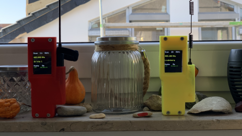
Finally conversation two, and it blew a lot of this out of the water. A guy showed me that he had re-programmed a LilyGo T-beam 433MHz LoRa radio made for the US to recieve AND decode the airsonde packets on 400MHz. The T-Beam has a built in GPS so I presume this is also telling you exact location and distance. Kind of like a thing I wanted to build, still I am keen to attempt my version at some stage. I was thinking either SDR to RasPi, or take the audio straight out of the UV-K5 and process it on an arduino or similar.
On Hackaday
TTGO T-Beam A TRACKER FOR RADIO SONDES
December 27, 2020 by Anool MahidhariaOn Hackaday
And ofcourse the code
- https://github.com/dl9rdz/rdz_ttgo_sonde
- which recommends a TTGO T-BEAM 1.0 (new version, with charger IC AXP192)
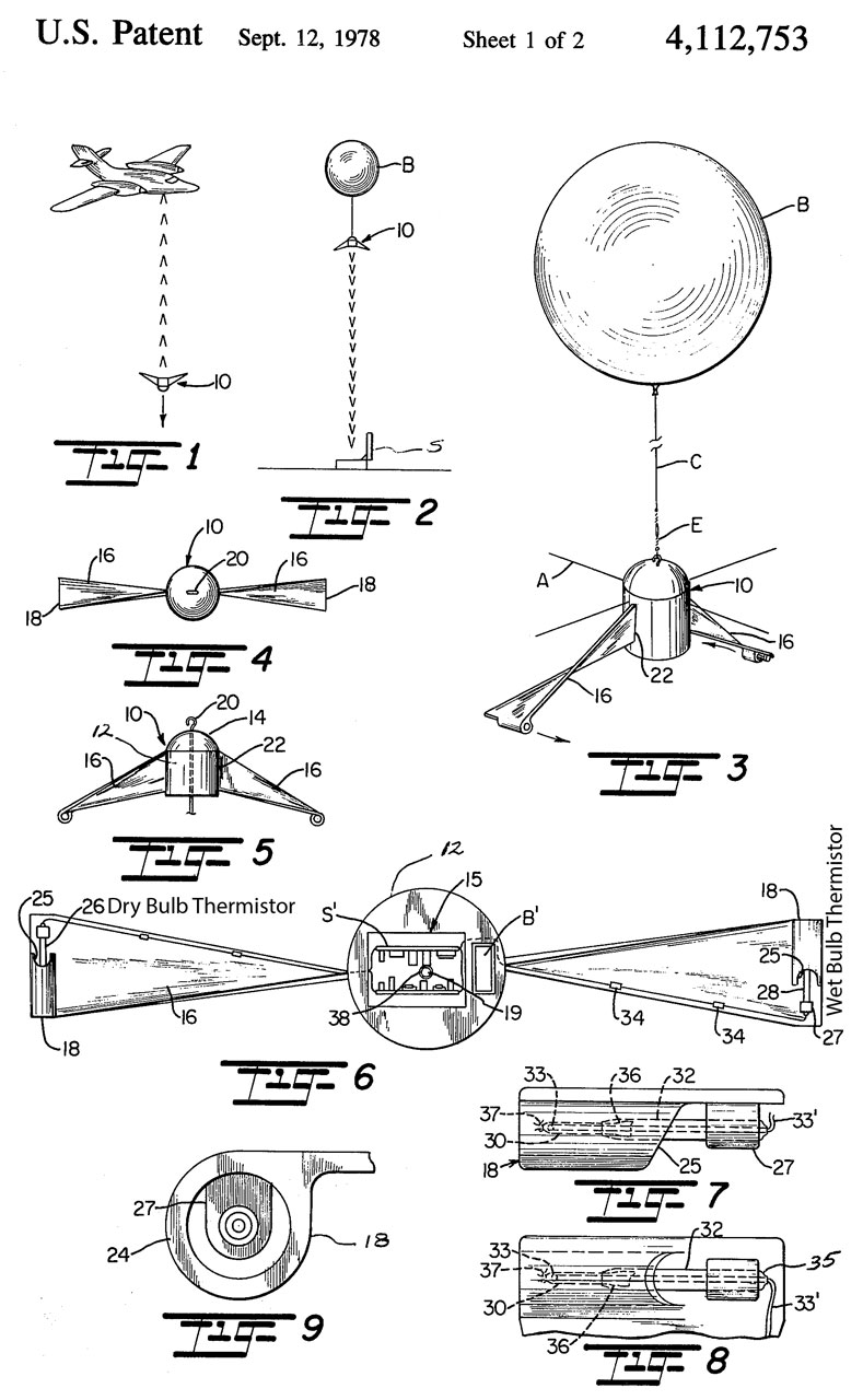
- whilst I’m here, a site with a bunch of interesting things about the actual
radiosondes and of all types
https://www.prc68.com/I/Radiosonde.html
Discussing SOTA
SOTA is Summits on the Air! where a summit is
A summit (or group of summits) must be at least 300 metres above sea level and have 150 metres prominence from the surrounding landscape.
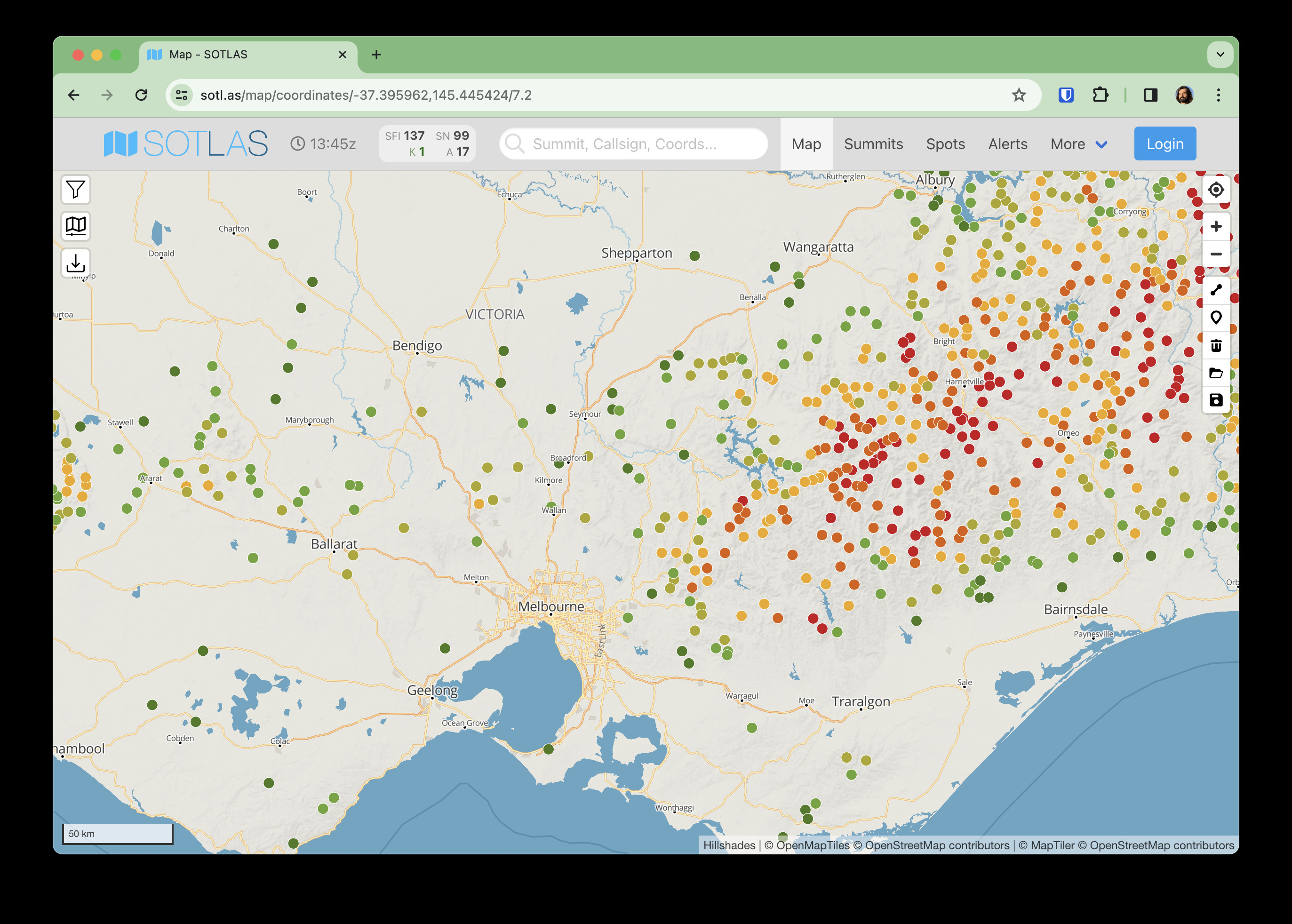
Sounds like there are a bunch of summits registered around the world, if you make 4 contacts within a 24 hour UTC day, you can register that with the sota site, sort of a competition I suppose.
Grounding antennas
I did get an answer to this, and it seems no one does anything to ground antennas from lighting. And the only story someone had was of someone moving a TV aerial when they got hit by lightning. So it sounds like just un-plugging it should be enough and maybe even the wire would be destroyed before it got to the HAM shack?
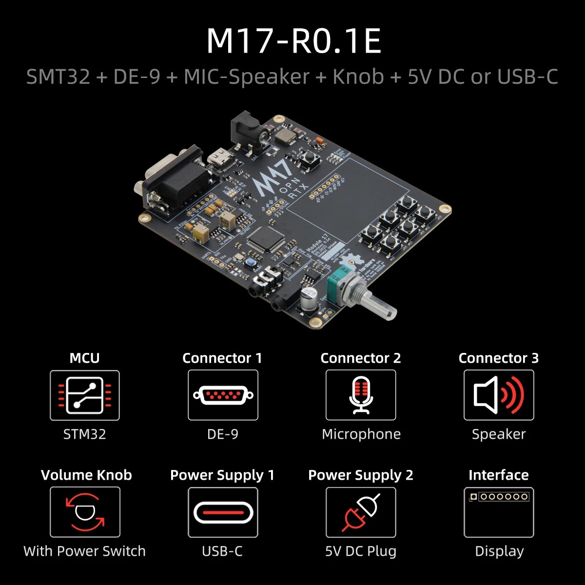
M17 digital radio modulation mode
And just after re-listening about codec2, there is M17
M17 is a digital radio modulation mode developed by Wojciech Kaczmarski (amateur radio call sign SP5WWP) and is primarily designed for voice communications on the VHF amateur radio bands, and above.
M17 uses Frequency-Division Multiple Access (FDMA) technology in which different communication streams are separated by frequency and run concurrently. It utilizes 4,800 symbols per second, 4-level frequency-shift keying (4FSK) with a root Nyquist filter applied to the bitstream.
M17 uses Codec 2, a low bitrate voice codec developed by David Rowe VK5DGR
and for a rainy day I suppose I should watch some more on this
M17 The Open Source Digital Mode For Ham Radio - Tech Minds

Module17 Standalone M17 Radio Modem For Ham Radio - Tech Minds

You can try M17 digital mode with just your phone - radiosification
